


Details
Beam Bridge
Construction Management Support, Executive plan
Location
S.S.3bis “Tiberina” 236+VI km
San Zaccaria (RA)
Principal
MONACO S.p.A.
Contracting company
IMPRENDITORI ASSOCIATI s.r.l.
(in association with MONACO S.p.A.)
BIT S.p.A. (metal works)
Team
Matildi+Partners srl
Activities
Construction plan (supplementary technical bypass report) – deck
Construction plan (supplementary technical bypass report) – shoulder reinforcement
Assistance to construction management
Time Period
2021
Extent and spans
87.2 m
23.6+40+23.6

Structural Layout

Structural Layout
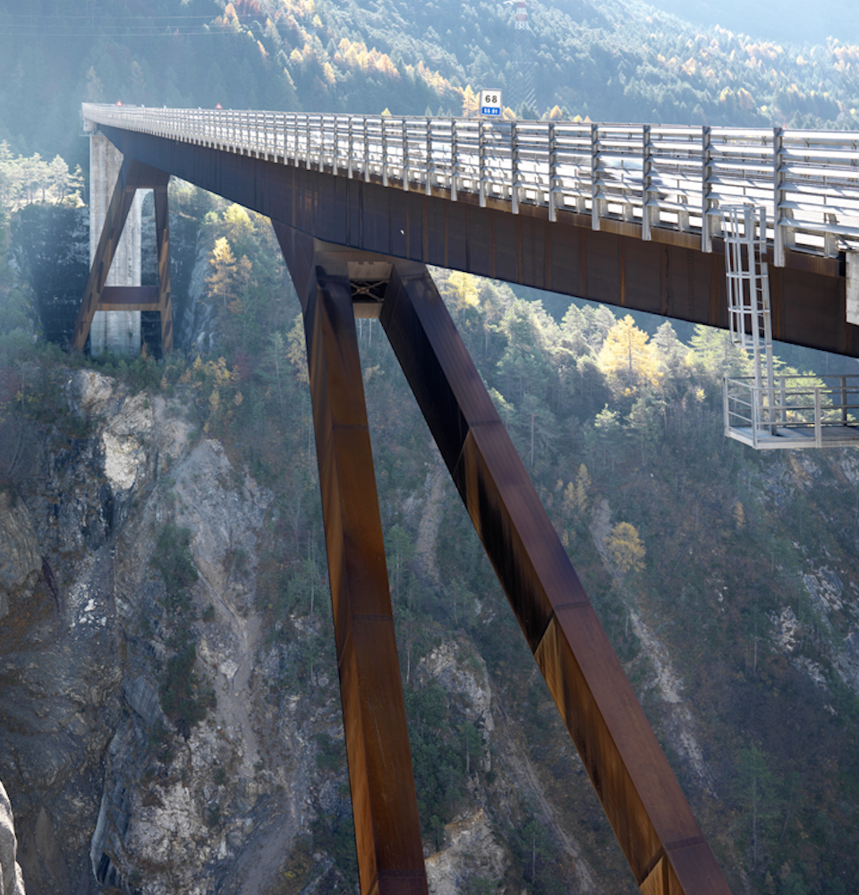
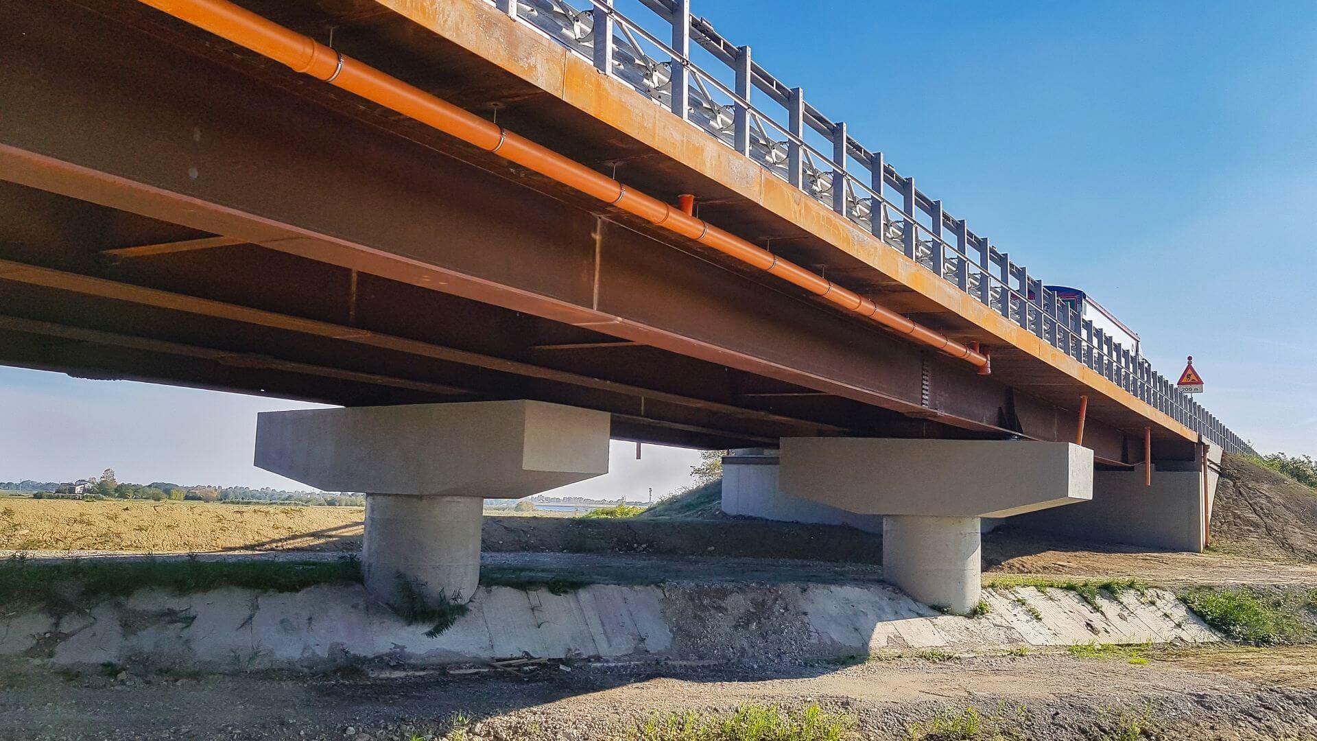
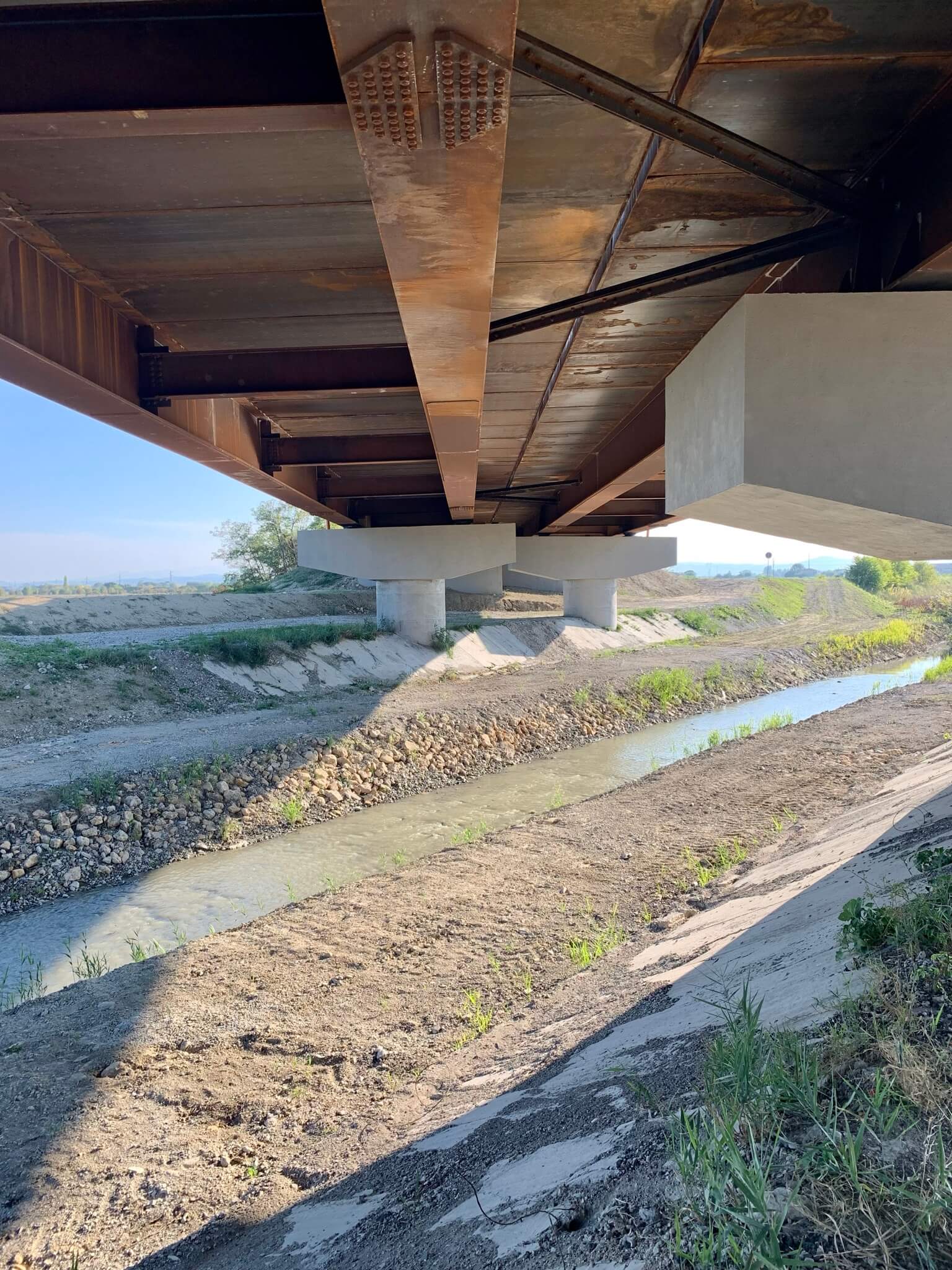
Construction plan for the bridge over the Bevano stream, located at 236+VI km on the S.S.3bis “Tiberina”: replacement of existing pre-stressed concrete/reinforced concrete decks with new ones in a composite steel-concrete system.
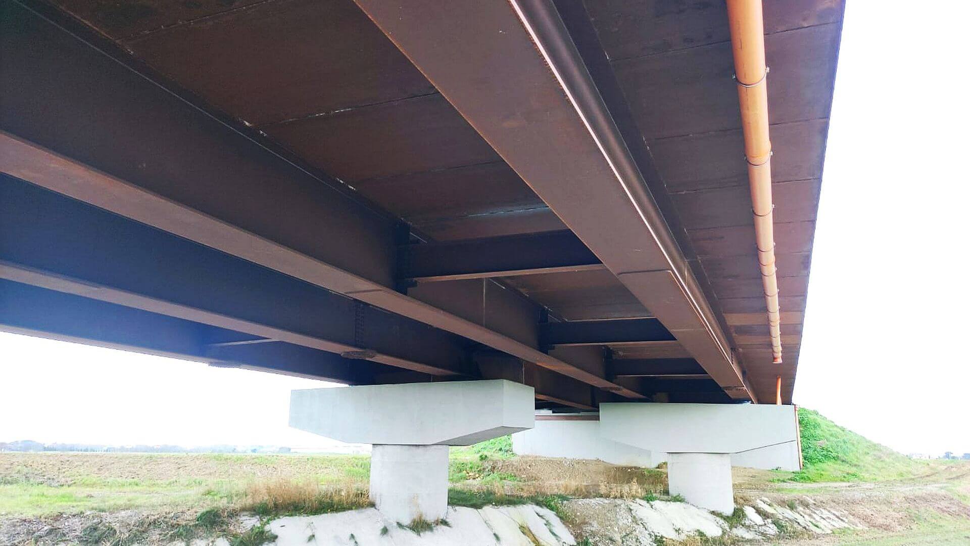
The two decks, separated by a 5 cm gap and longitudinally offset by approximately 12 m, (one in the Ravenna direction and the other in the Cesena direction) are continuous composite steel-concrete trusses in a composite steel-concrete system with a twin-beam pattern without intermediate stringer and a span sequence of 23.6+40+23.6 m.
The reinforced concrete slab is frame worked transversally over the beams and is cast on metal predalles.
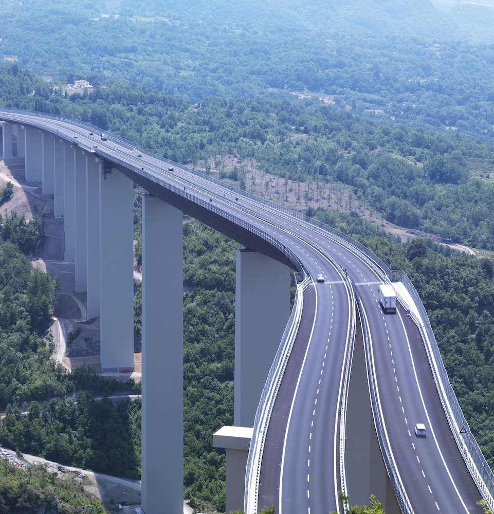
Its overall width is 8.29m for the Ravenna direction deck and 8.96m for the Cesena direction deck; the latter accommodates a New Jersey barrier separating the two decks. The outer curbs occupy 65cm and the remaining space is dedicated to the two traffic lanes.
The Deck
The Deck
The S355 steel beams are double-T sections in a welded assembly with a spacing of 4.4 m; the height varies from a minimum of 90 cm at the abutment to a maximum of 1.43 m in the centre span.
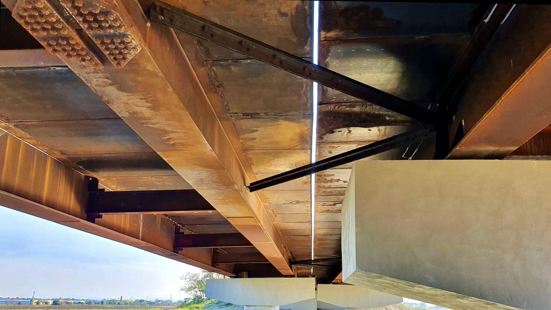
The diaphragms are arranged with typical spacing of 8 m; they consist of solid double-T sections in a welded assembly and bolted to the main beams.
Assembly and Launch
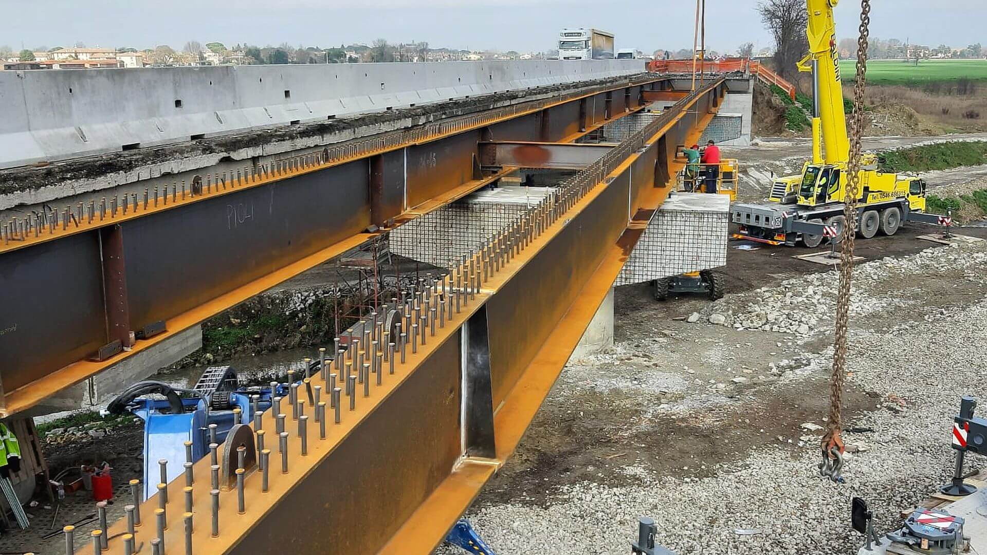
Assembly and Launch
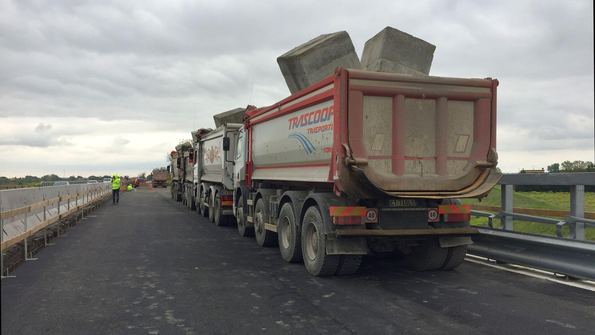
The decks were assembled and tested in two successive stages, keeping one of the two carriageways open to traffic; a launch was carried out from below with hoisting by crane of the macro-segments and crossbeams and then assembly of the main and secondary members at height using bolted joints.
In order to solve the issue of hammering between the two decks (as they are only 5 cm apart transversally), a floor trussing system consisting of angle braces was designed and constructed; these connect the pier diaphragms of one deck with the two beams (preceding and following) of the other. In this way, a synchronous horizontal displacement of the two structures is established with no constraints on vertical displacement due to deformations of the deck or routine maintenance work to replace supports.

